How to Choose an Insulation Resistance Tester?

Time:2026-09-23 Author:Ethan
0%

Choosing an Insulation Resistance Tester is not simply a matter of selecting the highest voltage or lowest price. The right instrument must match the equipment, test environment, and maintenance objective. A factory motor, photovoltaic cable, and building distribution panel can require different testing approaches.

Jim White, PE, an electrical safety specialist and trainer, notes, “The goal of electrical safety is to prevent injury and equipment damage.” That principle should guide every purchase. A reliable Insulation Resistance Tester should support suitable test voltages, stable readings, clear displays, and safe discharge after testing. It should also meet relevant requirements, such as IEC 61557-2, when applicable.

Look beyond the specification sheet. Check whether the tester offers 250 V, 500 V, 1,000 V, or higher settings. Confirm its measurement range and accuracy. A guard terminal can reduce surface leakage during difficult tests. Polarization index and dielectric absorption ratio functions may help evaluate aging insulation. However, these readings need technical judgment. A number alone does not explain why insulation has deteriorated.

Field experience also matters. Gloves, dust, long test leads, and a cold morning can affect the testing process. I have seen instruments appear convenient but become awkward inside crowded control cabinets. That weakness is easy to overlook.

This guide compares safety features, voltage capability, accuracy, portability, battery performance, calibration support, and total ownership cost. It also questions a common assumption: the most advanced tester is not always the best choice. The best Insulation Resistance Tester is the one technicians can use correctly, consistently, and safely.
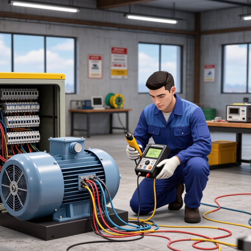
How to Choose an Insulation Resistance Tester?

What Is an Insulation Resistance Tester?

An insulation resistance tester is a specialized instrument for checking the condition of electrical insulation. It applies a controlled direct-current voltage between conductors and the ground, then measures tiny leakage currents. The result is usually shown in megohms. Higher resistance often indicates healthier insulation, but the number needs context. Moisture, dirt, temperature, cable length, and connected components can change the reading. The tester does not simply say “safe” or “unsafe.” It provides evidence for a trained decision.

In practical maintenance, technicians use these testers on motors, cables, switchboards, and industrial equipment. Before testing, isolate the circuit and discharge stored energy. Remove sensitive electronic devices when required. A stable connection matters. Loose clips can create misleading results. I have found that a clean probe and a dry surface sometimes matter more than selecting a higher test voltage. That detail is easy to overlook. A high reading can still mislead if the test setup is poor.

Tips: Choose a tester with suitable test voltages, a clear display, reliable leads, and automatic discharge. Check its measurement range against your equipment’s expected resistance. Follow the equipment manufacturer’s procedures and applicable electrical standards. Record temperature, humidity, voltage, and test duration. Do not compare readings blindly across different conditions. When results change sharply, stop and investigate. Insulation can deteriorate quietly.

How to Choose an Insulation Resistance Tester? — What Is an Insulation Resistance Tester?

An insulation resistance tester applies a controlled DC voltage to insulation and measures the resulting leakage current. The resistance is calculated using Ohm’s law: R = V ÷ I. Higher test voltages are commonly used for higher-voltage equipment, but the correct setting must always follow the equipment manufacturer’s safety and test requirements.

Example basis: a constant insulation resistance of 100 MΩ. At this resistance, a 50 V test produces 0.5 µA of leakage current, while a 1,000 V test produces 10 µA. Actual readings vary with insulation condition, temperature, moisture, cable length, and the equipment under test.

Which Electrical Specifications Should You Evaluate?

How to Choose an Insulation Resistance Tester?

When selecting an insulation resistance tester, examine its test voltage range first. Common settings include 250 V, 500 V, 1,000 V, and higher values. The correct voltage depends on the equipment’s insulation rating and maintenance procedure. Applying excessive voltage can damage sensitive circuits. Check the manufacturer’s service documentation before testing.

Accuracy matters when readings are near the acceptance limit. Review the resistance range, basic accuracy, and resolution together. A tester showing many digits is not automatically precise. Measure the expected range, not only the maximum value. Short-circuit current also deserves attention, especially when testing long cables or motor windings. Higher current may improve charging performance, but it can increase safety concerns. Discharge time is equally important after a test. The instrument should safely release stored energy from capacitive equipment.

Look for insulation diagnosis functions such as polarization index and dielectric absorption ratio. These readings can reveal moisture, contamination, or aging more clearly than one resistance value. I prefer testers that record test duration and voltage stability, because field notes are easy to misunderstand later. However, automated results still need professional judgment. I once trusted a stable reading too quickly and overlooked surface contamination near a terminal. The tester was not at fault. Check measurement categories, input protection, overvoltage tolerance, and operating temperature before purchase. A rugged case helps, but electrical protection matters more. Small details count.

How Do You Choose the Correct Test Voltage and Range?

How to Choose an Insulation Resistance Tester?

How Do You Choose the Correct Test Voltage and Range?

Choosing test voltage starts with the circuit’s rated voltage, insulation type, and equipment condition. For low-voltage installations, IEC 60364-6:2016 specifies 500 V DC testing for circuits up to 500 V, with a minimum insulation resistance of 1 MΩ. Circuits containing sensitive electronics may require 250 V DC instead. Always isolate electronic controls before testing. A higher voltage is not automatically better. It can stress aged insulation or damage connected devices.

Rotating machinery needs a more specific approach. IEEE 43-2013 recommends 500 V DC for windings rated below 1,000 V. Higher-rated windings require test voltages from 500 V to 10,000 V, depending on their insulation class and operating voltage. The same standard uses a one-minute insulation resistance reading and a polarization index based on ten-minute and one-minute results. A tester should therefore offer stable timing, automatic range selection, and resistance measurement extending into the gigohm range. Small details matter, especially when cable runs are long.

Field experience shows that moisture, surface dirt, and temperature can change readings dramatically. Clean and dry the test point first. Record temperature with every result. IEC 60085 indicates that insulation aging accelerates as temperature rises, although correction methods vary by equipment. I sometimes prefer a lower preliminary test before the full voltage. It adds time. It may prevent a costly mistake. Standards guide the decision, but the equipment manual and maintenance history should control the final setting.

How to Choose an Insulation Resistance Tester? - How Do You Choose the Correct Test Voltage and Range?

Decision Dimension Recommended Selection Typical Application or Condition Important Consideration
50 V DC test voltage Choose when the circuit contains sensitive electronic components or very low-voltage wiring. Communication circuits, control wiring, sensors, and selected extra-low-voltage circuits. Confirm that the connected equipment is approved for insulation testing; disconnect electronic devices whenever required.
100 V DC test voltage Use for low-voltage control and instrumentation circuits when 50 V is insufficient and a low-stress test is preferred. Control panels, signal wiring, and low-voltage assemblies. The correct voltage depends on the equipment documentation and the applicable test standard.
250 V DC test voltage Choose for low-voltage circuits and equipment that should not receive a 500 V insulation test. Some electronic or control equipment, low-voltage cables, and selected building services. Avoid applying the test across surge protection devices, variable-speed drives, PLCs, power supplies, or other connected electronics unless permitted.
500 V DC test voltage Select for many conventional low-voltage installations and equipment rated up to approximately 500 V, subject to the governing standard. Low-voltage power cables, distribution circuits, motors, transformers, and switchgear. This is a common field setting, but the equipment rating and test procedure must always take priority.
1,000 V DC test voltage Choose for higher-voltage low-voltage equipment and certain motor or cable tests when specified by the manufacturer or standard. Motors, generators, cables, and equipment with insulation systems designed for higher test stress. Do not infer the test voltage only from the nominal operating voltage; verify the prescribed maintenance or acceptance-test value.
2,500 V DC test voltage Use for selected medium-voltage equipment and rotating machines when the insulation system and test procedure permit it. Medium-voltage motors, generators, transformers, and cables. High-voltage testing requires suitable clearances, isolation, discharge time, and trained personnel.
5,000 V DC test voltage Select for higher-voltage rotating machines, cables, and electrical apparatus when required by the applicable test standard. Medium-voltage and higher-rated insulation systems. Use guarded test leads and controlled access; capacitive equipment can retain a dangerous charge after testing.
10,000 V DC test voltage Choose only when the equipment documentation or recognized test standard specifically calls for it. Specialized high-voltage cables, large rotating machines, and high-voltage insulation systems. This setting is not a general-purpose upgrade; excessive test voltage may overstress aged or contaminated insulation.
Resistance measurement range: MΩ Ensure the tester can measure from at least 1 MΩ upward with suitable accuracy. Basic continuity-related insulation checks and older or contaminated low-voltage equipment. A low reading may indicate moisture, dirt, damaged insulation, or an unintended connected load.
Resistance measurement range: tens to hundreds of MΩ Choose a tester with a stable, clearly readable range covering the expected pass values. Routine testing of low-voltage cables, motors, transformers, and electrical installations. Compare results with the equipment specification, previous readings, temperature, and test duration rather than using one universal pass value.
Resistance measurement range: GΩ Select a high-range instrument when testing clean, dry, modern, or high-voltage insulation. New cables, high-voltage apparatus, large rotating machines, and diagnostic maintenance testing. At very high resistance, surface leakage, humidity, cable length, lead insulation, and guarding can affect the result.
Automatic voltage ramp or selectable steps Choose a tester with controlled voltage ramping when testing large or capacitive equipment. Long cables, motors, generators, transformers, and equipment with significant capacitance. A controlled ramp reduces sudden charging current and makes the test easier to monitor.
Guard terminal Select a guarded tester when surface leakage could distort high-resistance measurements. Dirty insulators, damp surfaces, cable terminations, bushings, and large machines. The guard diverts surface leakage from the measurement circuit; it does not replace cleaning and drying.
Timed test and polarization index Choose timed recording when insulation condition and trend analysis are more important than a single reading. Motors, generators, transformers, and maintenance programs. Polarization Index is commonly calculated as R10 min ÷ R1 min; interpretation depends on the equipment type, insulation system, temperature, and standard.
Temperature and trend compensation Prefer data logging and temperature records for condition-based maintenance. Comparing repeated tests on motors, cables, and transformers over time. Insulation resistance generally decreases as temperature rises; comparisons should use consistent conditions or an accepted correction method.
Discharge and safety functions Choose automatic discharge, live-circuit detection, overvoltage protection, and clear warning indicators. Any test involving cables, motors, transformers, capacitors, or other energy-storing equipment. Verify zero voltage before touching the circuit, apply grounding procedures, and follow the site’s lockout/tagout requirements.
Selection rule: Choose the lowest test voltage that meets the applicable standard and equipment documentation, then select a resistance range that comfortably covers both the expected reading and the instrument’s required accuracy. Disconnect sensitive electronic equipment before applying an insulation test.

Which Safety Features and Standards Should You Check?

Choosing an insulation resistance tester starts with safety ratings, not maximum test voltage. Look for compliance with IEC 61557-2, which covers insulation resistance measurement in low-voltage systems. The instrument should also meet IEC 61010-1 requirements for electrical measurement equipment. Check its measurement category carefully. CAT III suits distribution circuits, while CAT IV is intended for service entrances and outdoor conductors. A higher number is not automatically safer.

Useful protections include automatic live-circuit detection, guarded terminals, test inhibition, and automatic discharge after testing. The discharge function matters when a long cable stores energy. Touching it too soon can create a sharp, unexpected shock. In 2022, the U.S. Bureau of Labor Statistics recorded 145 workplace deaths caused by exposure to electricity in its Census of Fatal Occupational Injuries. That figure makes a warning light feel less like a convenience. It is a control.

Look for clear voltage selection, a lockable test switch, insulated probes, and a visible battery warning. Verify calibration records traceable to ISO/IEC 17025 laboratories. Ask whether the stated accuracy applies across the full temperature range, not only in a quiet laboratory. I once trusted a clean display too quickly. That was careless. Moisture, surface contamination, and lead condition can distort readings. The tester should support controlled discharge and stable measurements under field conditions. Safety claims deserve verification in the manual, certificate, and test procedure, not just on the front panel.

How Can You Match the Tester to Your Testing Applications?

How to Choose an Insulation Resistance Tester?

Matching an insulation resistance tester to the application matters more than choosing the highest advertised voltage. A technician testing a motor winding needs different functions from someone checking control wiring. Start with the equipment’s rated voltage and the insulation condition expected in service. For low-voltage panels, selectable test voltages help prevent unnecessary stress. A fixed, excessive voltage can produce misleading results or damage sensitive components.

For long cables, choose a tester with a suitable resistance range, stable leads, and clear readings in noisy environments. Guard terminals can reduce surface leakage during tests on dirty or damp insulation. Motors and transformers may require timed tests, polarization index, or dielectric absorption measurements. These functions reveal slow insulation behavior that a quick reading can miss. They are useful, not magical.

Battery life and physical design also affect field accuracy. A bright display helps inside cramped cabinets. Strong leads and well-insulated probes reduce handling errors. Check whether the tester can discharge the circuit automatically after testing. It should also meet relevant electrical safety requirements and include traceable calibration information.

A common mistake is matching the tester only to the asset name. The actual cable length, temperature, moisture, and access conditions can change the choice. I would record these details before purchasing. Test results should be compared with manufacturer guidance, previous readings, and site procedures. One reading rarely tells the whole story. Interpretation requires context.

FAQS

How do you choose the correct test voltage?

Start with the circuit’s rated voltage and insulation condition. For circuits up to 500 V, 500 V DC is commonly specified. Sensitive electronics may need 250 V DC. Higher voltage is not always better.

Should electronic controls remain connected during testing?

No. Isolate electronic controls before applying test voltage. A connected device may suffer damage, even during a short test.

What test voltage suits rotating machinery?

Windings below 1,000 V commonly use 500 V DC. Higher-rated windings may require 500 V to 10,000 V. Follow the equipment manual and insulation class.

What measurement range should the tester provide?

Choose a tester reaching the gigohm range for motors and long cables. Automatic range selection helps prevent missed readings. Stable timing also supports one-minute tests and polarization index checks.

How do moisture and temperature affect readings?

Moisture, dirt, and heat can change results sharply. Clean and dry the test point. Record temperature with every reading.

Which safety features are important?

Look for live-circuit detection, guarded terminals, test inhibition, and automatic discharge. Insulated probes and a lockable test switch add practical protection. The discharge function matters with long cables.

How should measurement categories be selected?

CAT III suits distribution circuits. CAT IV is intended for service entrances and outdoor conductors. A higher category is not automatically safer.

How can you verify tester accuracy?

Check calibration records linked to an ISO/IEC 17025 laboratory. Confirm accuracy across the stated temperature range. A clean display can still show a misleading result.

Should you perform a lower-voltage preliminary test?

Sometimes, yes. A lower preliminary test can reveal problems before full voltage is applied. It takes extra time, but I would not skip it on aged insulation.

Conclusion

Choosing the right Insulation Resistance Tester begins with understanding its purpose: measuring the resistance of electrical insulation to help identify moisture, aging, contamination, or potential leakage paths. When comparing models, evaluate key electrical specifications such as resistance measurement range, accuracy, test current, voltage stability, response time, and display resolution. These factors determine whether the instrument can provide reliable results for simple maintenance checks or more demanding diagnostic work.

The correct test voltage and measurement range should match the equipment under examination and the manufacturer’s recommendations, avoiding unnecessary stress on sensitive components. Safety is equally important, so check for automatic discharge, overvoltage protection, clear warning indicators, insulated test leads, and compliance with relevant electrical safety standards. Finally, match the tester to your application, whether it involves cables, motors, transformers, control panels, or routine preventive maintenance. A practical choice should balance measurement performance, ease of use, portability, durability, and operator protection.

Ethan

Ethan

Ethan is a seasoned marketing professional with a deep expertise in our company's innovative product line. With a passion for sharing knowledge and insights, he takes the lead in regularly updating our corporate blog, where he explores industry trends, product features, and effective marketing......